7. ジョイントの種類とジョイント関数
7.1. ジョイントの生成と破壊
dJointID dJointCreateBall (dWorldID, dJointGroupID);
dJointID dJointCreateHinge (dWorldID, dJointGroupID);
dJointID dJointCreateSlider (dWorldID, dJointGroupID);
dJointID dJointCreateContact (dWorldID, dJointGroupID,
                             const dContact *);
dJointID dJointCreateUniversal (dWorldID, dJointGroupID);
dJointID dJointCreateHinge2 (dWorldID, dJointGroupID);
dJointID dJointCreateFixed (dWorldID, dJointGroupID);
dJointID dJointCreateAMotor (dWorldID, dJointGroupID);
与えられた種類の新しいジョイントを生成する。ジョイントは、最初、どのの剛体にも接続していないので、「リンボ状態」(つまり、シミュレーションで効果を持っていない状態)である。ジョイントグループIDは通常のジョイントを割り付けるには0である。それがゼロでない場合、ジョイントは与えられたジョイントグループの中で割り付けられる。接触ジョイントは与えられたdContact構造体と一緒に初期化される。
void dJointDestroy (dJointID);
ジョイントの破棄をする。接続された剛体から切断して、世界から削除を行う。しかしながら、そのジョイントがグループのメンバである場合、この関数は効果を持たない。グループを空もしくは破壊しない限りジョイントを破壊することはできない。
dJointGroupID dJointGroupCreate (int max_size);
ジョイントグループを作成する。max_size引数は、現在は使われていないので、0に設定する。これは旧バージョンとの互換性を保つためにある。
void dJointGroupDestroy (dJointGroupID);
ジョイントグループを破壊する。ジョイントグループの中にある全てのジョイントは 破壊される。
void dJointGroupEmpty (dJointGroupID);
ジョイントグループを空にする。ジョイントグループ中にあるジョイントはすべて破棄される。しかし、ジョイントグループ自身は破棄されない。
7.2. 様々なジョイント関数
void dJointAttach (dJointID, dBodyID body1, dBodyID body2);
新しい剛体のためのジョイントの取り付け。ジョイントがすでに接続されている場合、これは最初に古い剛体から取り外される。1つの剛体のためのジョイントを取り付けるためにはゼロをbody1もしくはbody2を設定する。ゼロの剛体は静的な環境に属するものとする。両方にゼロを設定することは「リンボ状態」の中へジョイントを入れることになるので、これはシミュレーション上で効果を持たなくなる。
いくつかのジョイントは、hinge-2のように2つの剛体への取り付けが必要である。
void dJointSetData (dJointID, void *data);
void *dJointGetData (dJointID);
ジョイントのユーザデータ・ポインタの設定と取得。
int dJointGetType (dJointID);
ジョイントのタイプを取得する。次の定数のうちの1つが返される:
| dJointTypeBall | ボール-ソケット(ball and socket)ジョイント |
| dJointTypeHinge | ヒンジ(hinge)ジョイント |
| dJointTypeSlider | スライダ(slider)ジョイント |
| dJointTypeContact | 接触(contact)ジョイント |
| dJointTypeUniversal | ユニバーサル(universal)ジョイント |
| dJointTypeHinge2 | ヒンジ2(hinge-2)ジョイント |
| dJointTypeFixed | 固定(fixed)ジョイント |
| dJointTypeAMotor | 角度モータ(angular motor)ジョイント |
dBodyID dJointGetBody (dJointID, int index);
このジョイントに接続される剛体を返す。indexが0で「第一」の剛体が返される場合、dJointAttachのbody1引数に対応している。indexが1で「第二」の剛体が返される場合、dJointAttachのbody2引数に対応している。
これらの1つが返した剛体のIDがゼロである場合、ジョイントは静的な環境と剛体とを接続している。両方の剛体IDがゼロの場合、そのジョイントは「リンボ」であるか、シミュレーションで何の効果も持たないものである。
void dJointSetFeedback (dJointID, dJointFeedback *);
dJointFeedback *dJointGetFeedback (dJointID);
世界の時間ステップの間、各ジョイントによって適用される力は計算される。これらの力は、連結された剛体に直接加えられ、ユーザは通常、どのジョイントがどのように力を与えたかを知る術を持たない。
この情報が要求される場合、ユーザはdJointFeedback構造体を割り当てることができ、そのポインタをdJointSetFeedback()関数へ渡す。フィードバック情報構造体は以下のように定義される:
typedef struct dJointFeedback {
  dVector3 f1;       // force that joint applies to body 1
  dVector3 t1;       // torque that joint applies to body 1
  dVector3 f2;       // force that joint applies to body 2
  dVector3 t2;       // torque that joint applies to body 2
} dJointFeedback;
During the time step any feedback structures that are attached to joints will be filled in with the joint's force and torque information. The dJointGetFeedback() function returns the current feedback structure pointer, or 0 if none is used (this is the default). dJointSetFeedback() can be passed 0 to disable feedback for that joint.
時間ステップの間で、ジョイントに取り付けられるどのフィードバック構造体もジョイントの力およびトルク情報が書き入込まれる。 dJointGetFeedback()関数は現在のフィードバック構造ポインタを返すか、あるいは、どれも使用されない場合は0を返す(これはデフォルト)。dJointSetFeedback()は、そのジョイントのためのフィードバックを無効にするために0を渡すことができる。
時間ステップの間で、ジョイントに取り付けられるどのフィードバック構造体もジョイントの力およびトルク情報が書き入込まれる。 dJointGetFeedback()関数は現在のフィードバック構造ポインタを返すか、あるいは、どれも使用されない場合は0を返す(これはデフォルト)。dJointSetFeedback()は、そのジョイントのためのフィードバックを無効にするために0を渡すことができる。
Now for some API design notes. It might seem strange to require that users perform the allocation of these structures. Why not just store the data statically in each joint? The reason is that not all users will use the feedback information, and even when it is used not all joints will need it. It will waste memory to store it statically, especially as this structure could grow to store a lot of extra information in the future.
現在、いくつかのAPIの設計に関しては注意する必要がある。それはユーザが構造体の割り当てる必要があるのは変に思われるかもしれない。なぜ各ジョイントにおいて静的なデータを保存するだけではないのだろうか。その理由は、全てのユーザがフィードバック情報を使うわけではなく、また、それが使用されるときでさえ、すべてのジョイントがそれを必要とするわけではない。それは静的なデータを保存するためにメモリを消費して、この構造体で特に多くの情報を保存するために今後大きくなることもあり得る。
現在、いくつかのAPIの設計に関しては注意する必要がある。それはユーザが構造体の割り当てる必要があるのは変に思われるかもしれない。なぜ各ジョイントにおいて静的なデータを保存するだけではないのだろうか。その理由は、全てのユーザがフィードバック情報を使うわけではなく、また、それが使用されるときでさえ、すべてのジョイントがそれを必要とするわけではない。それは静的なデータを保存するためにメモリを消費して、この構造体で特に多くの情報を保存するために今後大きくなることもあり得る。
Why not have ODE allocate the structure itself, at the user's request? The reason is that contact joints (which are created and destroyed every time step) would require a lot of time to be spent in memory allocation if feedback is required. Letting the user do the allocation means that a better allocation strategy can be provided, e.g simply allocating them out of a fixed array.
ユーザの要請で、なぜODEにそれ構造体自体を割り当てさせないのか。その理由は、フィードバックが必要な場合に、接触ジョイントが(毎ステップで生成と破壊を繰り返す間)メモリ割り当てに費されるべき多くの時間も必要とするためである。ユーザに割り当てさせることは、より良い割り当て方法が提供できることを意味する。したがって、単に固定配列からそれらを割り当てる。
ユーザの要請で、なぜODEにそれ構造体自体を割り当てさせないのか。その理由は、フィードバックが必要な場合に、接触ジョイントが(毎ステップで生成と破壊を繰り返す間)メモリ割り当てに費されるべき多くの時間も必要とするためである。ユーザに割り当てさせることは、より良い割り当て方法が提供できることを意味する。したがって、単に固定配列からそれらを割り当てる。
The alternative to this API is to have a joint-force callback. This would work of course, but it has a few problems. First, callbacks tend to pollute APIs and sometimes require the user to go through unnatural contortions to get the data to the right place. Second, this would expose ODE to being changed in the middle of a step (which would have bad consequences), and there would have to be some kind of guard against this or a debugging check for it - which would complicate things.
このAPIの代替物は、ジョイント力のコールバックすることである。もちろんこれは動作するが、いくつか問題がある。1つは、コールバックはAPIを汚す傾向があり、ときどき適切な場所にデータを取得するために不自然なゆがみを行うことをユーザーに要求する。2つめに、これは(良い結果を持たないので)ステップの変化するときにODEを爆発させる可能性がある。そして、これらは煩わしいが、何らかのガード違反やデバッグチェックを持つ必要があるだろう。
このAPIの代替物は、ジョイント力のコールバックすることである。もちろんこれは動作するが、いくつか問題がある。1つは、コールバックはAPIを汚す傾向があり、ときどき適切な場所にデータを取得するために不自然なゆがみを行うことをユーザーに要求する。2つめに、これは(良い結果を持たないので)ステップの変化するときにODEを爆発させる可能性がある。そして、これらは煩わしいが、何らかのガード違反やデバッグチェックを持つ必要があるだろう。
int dAreConnected (dBodyID, dBodyID);
ユーティリティ関数。2つの剛体がジョイントによって接続されているとき1を返して、そうでない場合は0を返す。
int dAreConnectedExcluding (dBodyID, dBodyID, int joint_type);
Utility function: return 1 if the two bodies are connected together by a joint that does not have type joint_type, otherwise return 0. joint_type is a dJointTypeXXX constant. This is useful for deciding whether to add contact joints between two bodies: if they are already connected by non-contact joints then it may not be appropriate to add contacts, however it is okay to add more contact between- bodies that already have contacts.
ユーティリティ関数。2つの剛体が "joint_type" でないジョイントによって接続される場合は1を返す。そうでなければ0を返す。"joint_type" はdJointTypeXXXの定数である。これは、2つの剛体間の接触ジョイントを加えるべきかどうか決定するのに役立つ: それらがそのとき非接触ジョイントによって既に接続される場合、接触を加えることは適切ではないかもしれない。しかしながら、より多くの接触を既に接触を持っている剛体間に加えることはよい。
ユーティリティ関数。2つの剛体が "joint_type" でないジョイントによって接続される場合は1を返す。そうでなければ0を返す。"joint_type" はdJointTypeXXXの定数である。これは、2つの剛体間の接触ジョイントを加えるべきかどうか決定するのに役立つ: それらがそのとき非接触ジョイントによって既に接続される場合、接触を加えることは適切ではないかもしれない。しかしながら、より多くの接触を既に接触を持っている剛体間に加えることはよい。
7.3. ジョイントパラメータを設定する関数
7.3.1. ボールとソケット
図4にボール-ソケットジョイントを示す。
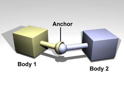
図4: ボール-ソケットジョイント
void dJointSetBallAnchor (dJointID, dReal x, dReal y, dReal z);
ジョイントのアンカー点を設定する。ジョイントは各剛体とともにその点に留まろうとする。入力は世界座標において指定される。
void dJointGetBallAnchor (dJointID, dVector3 result);
Get the joint anchor point, in world coordinates. This returns the point on body 1. If the joint is perfectly satisfied, this will be the same as the point on body 2.
世界座標でのジョイントのアンカー点を取得する。これは剛体1の点を返す。ジョイントが全て満たされている場合、これは剛体2の点と同じだろう。
世界座標でのジョイントのアンカー点を取得する。これは剛体1の点を返す。ジョイントが全て満たされている場合、これは剛体2の点と同じだろう。
void dJointGetBallAnchor2 (dJointID, dVector3 result);
Get the joint anchor point, in world coordinates. This returns the point on body 2. You can think of a ball and socket joint as trying to keep the result of dJointGetBallAnchor() and dJointGetBallAnchor2() the same. If the joint is perfectly satisfied, this function will return the same value as dJointGetBallAnchor to within roundoff errors. dJointGetBallAnchor2 can be used, along with dJointGetBallAnchor, to see how far the joint has come apart.
世界座標でジョイントのアンカー点を取得する。これは剛体2における点を返す。dJointGetBallAnchor()とdJointGetBallAnchor2()の結果を維持しようとボール-ソケットジョイントについて考えることができる。 ジョイントが完全に満足される場合、この関数は丸め誤差以内でdJointGetBallAnchorと同じ値を返す。バラバラなジョイントがどれくらいの離れているかを見るために、dJointGetBallAnchorと一緒に、dJointGetBallAnchor2は使用することができ、
世界座標でジョイントのアンカー点を取得する。これは剛体2における点を返す。dJointGetBallAnchor()とdJointGetBallAnchor2()の結果を維持しようとボール-ソケットジョイントについて考えることができる。 ジョイントが完全に満足される場合、この関数は丸め誤差以内でdJointGetBallAnchorと同じ値を返す。バラバラなジョイントがどれくらいの離れているかを見るために、dJointGetBallAnchorと一緒に、dJointGetBallAnchor2は使用することができ、
7.3.2. ヒンジ(hinge)
A hinge joint is shown in figure 5.
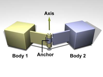
Figure 5: A hinge joint.
void dJointSetHingeAnchor (dJointID, dReal x, dReal y, dReal z);
void dJointSetHingeAxis (dJointID, dReal x, dReal y, dReal z);
Set hinge anchor and axis parameters.
ヒンジのアンカーと軸のパラメータを設定する。
ヒンジのアンカーと軸のパラメータを設定する。
void dJointGetHingeAnchor (dJointID, dVector3 result);
Get the joint anchor point, in world coordinates. This returns the point on body 1. If the joint is perfectly satisfied, this will be the same as the point on body 2.
世界の座標でジョイントのアンカー点を取得する。これはBody1上の 点を返す。ジョイントが完全に満たされている場合、これはBody2上の点と同じになる。
世界の座標でジョイントのアンカー点を取得する。これはBody1上の 点を返す。ジョイントが完全に満たされている場合、これはBody2上の点と同じになる。
void dJointGetHingeAnchor2 (dJointID, dVector3 result);
Get the joint anchor point, in world coordinates. This returns the point on body 2. If the joint is perfectly satisfied, this will return the same value as dJointGetHingeAnchor. If not, this value will be slightly different. This can be used, for example, to see how far the joint has come apart.
void dJointGetHingeAxis (dJointID, dVector3 result);
Get hinge axis parameter.
ヒンジの軸のパラメータを取得する。
ヒンジの軸のパラメータを取得する。
dReal dJointGetHingeAngle (dJointID);
dReal dJointGetHingeAngleRate (dJointID);
Get the hinge angle and the time derivative of this value. The angle is measured between the two bodies, or between the body and the static environment. The angle will be between -pi..pi.
When the hinge anchor or axis is set, the current position of the attached bodies is examined and that position will be the zero angle.
7.3.3. Slider
A slider joint is shown in figure 6.
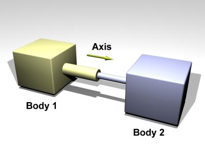
Figure 6: A slider joint.
void dJointSetSliderAxis (dJointID, dReal x, dReal y, dReal z);
Set the slider axis parameter.
スライダーの軸パラメータを設定する。
スライダーの軸パラメータを設定する。
void dJointGetSliderAxis (dJointID, dVector3 result);
Get the slider axis parameter.
スライダーの軸パラメータを取得する。
スライダーの軸パラメータを取得する。
dReal dJointGetSliderPosition (dJointID);
dReal dJointGetSliderPositionRate (dJointID);
Get the slider linear position (i.e. the slider's ``extension'') and the time derivative of this value.
スライダーの線形位置(つまり、スライダーの"伸長")と、この値の時 間的変化取得する。
スライダーの線形位置(つまり、スライダーの"伸長")と、この値の時 間的変化取得する。
When the axis is set, the current position of the attached bodies is examined and that position will be the zero position.
軸が設定されている場合、剛体を繋げている現在の位置を調べて、その位 置を初期位置とする。
軸が設定されている場合、剛体を繋げている現在の位置を調べて、その位 置を初期位置とする。
7.3.4. Universal
A universal joint is shown in figure 7.
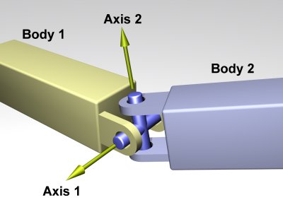
Figure 7: A universal joint.
A universal joint is like a ball and socket joint that constrains an extra degree of rotational freedom. Given axis 1 on body 1, and axis 2 on body 2 that is perpendicular to axis 1, it keeps them perpendicular. In other words, rotation of the two bodies about the direction perpendicular to the two axes will be equal.
In the picture, the two bodies are joined together by a cross. Axis 1 is attached to body 1, and axis 2 is attached to body 2. The cross keeps these axes at 90 degrees, so if you grab body 1 and twist it, body 2 will twist as well.
A Universal joint is equivalent to a hinge-2 joint where the hinge-2's axes are perpendicular to each other, and with a perfectly rigid connection in place of the suspension.
Universal joints show up in cars, where the engine causes a shaft, the drive shaft, to rotate along its own axis. At some point you'd like to change the direction of the shaft. The problem is, if you just bend the shaft, then the part after the bend won't rotate about its own axis. So if you cut it at the bend location and insert a universal joint, you can use the constraint to force the second shaft to rotate about the same angle as the first shaft.
Another use of this joint is to attach the arms of a simple virtual creature to its body. Imagine a person holding their arms straight out. You may want the arm to be able to move up and down, and forward and back, but not to rotate about its own axis.
Here are the universal joint functions:
void dJointSetUniversalAnchor (dJointID, dReal x, dReal y, dReal z);
void dJointSetUniversalAxis1 (dJointID, dReal x, dReal y, dReal z);
void dJointSetUniversalAxis2 (dJointID, dReal x, dReal y, dReal z);
Set universal anchor and axis parameters. Axis 1 and axis 2 should be perpendicular to each other.
void dJointGetUniversalAnchor (dJointID, dVector3 result);
Get the joint anchor point, in world coordinates. This returns the point on body 1. If the joint is perfectly satisfied, this will be the same as the point on body 2.
void dJointGetUniversalAnchor2 (dJointID, dVector3 result);
Get the joint anchor point, in world coordinates. This returns the point on body 2. You can think of the ball and socket part of a universal joint as trying to keep the result of dJointGetBallAnchor() and dJointGetBallAnchor2() the same. If the joint is perfectly satisfied, this function will return the same value as dJointGetUniversalAnchor to within roundoff errors. dJointGetUniversalAnchor2 can be used, along with dJointGetUniversalAnchor, to see how far the joint has come apart.
void dJointGetUniversalAxis1 (dJointID, dVector3 result);
void dJointGetUniversalAxis2 (dJointID, dVector3 result);
Get univeral axis parameters.
7.3.5. Hinge-2
A hinge-2 joint is shown in figure 8.

Figure 8: A hinge-2 joint.
The hinge-2 joint is the same as two hinges connected in series, with different hinge axes. An example, shown in the above picture is the steering wheel of a car, where one axis allows the wheel to be steered and the other axis allows the wheel to rotate.
hinge-2ジョイントは、2つのヒンジの異なる軸を直列に接続した のと同じである。例として、上記の写真に自動車のハンドルを示す。車輪が操縦部を1つの軸で表現し、別の軸で車輪の回転部を表現している。
hinge-2ジョイントは、2つのヒンジの異なる軸を直列に接続した のと同じである。例として、上記の写真に自動車のハンドルを示す。車輪が操縦部を1つの軸で表現し、別の軸で車輪の回転部を表現している。
The hinge-2 joint has an anchor point and two hinge axes. Axis 1 is specified relative to body 1 (this would be the steering axis if body 1 is the chassis). Axis 2 is specified relative to body 2 (this would be the wheel axis if body 2 is the wheel).
Axis 1 can have joint limits and a motor, axis 2 can only have a motor.
Axis 1 can function as a suspension axis, i.e. the constraint can be compressible along that axis.
The hinge-2 joint where axis1 is perpendicular to axis 2 is equivalent to a universal joint with added suspension.
void dJointSetHinge2Anchor (dJointID, dReal x, dReal y, dReal z);
void dJointSetHinge2Axis1 (dJointID, dReal x, dReal y, dReal z);
void dJointSetHinge2Axis2 (dJointID, dReal x, dReal y, dReal z);
Set hinge-2 anchor and axis parameters. Axis 1 and axis 2 must not lie along the same line.
void dJointGetHinge2Anchor (dJointID, dVector3 result);
Get the joint anchor point, in world coordinates. This returns the point on body 1. If the joint is perfectly satisfied, this will be the same as the point on body 2.
void dJointGetHinge2Anchor2 (dJointID, dVector3 result);
Get the joint anchor point, in world coordinates. This returns the point on body 2. If the joint is perfectly satisfied, this will return the same value as dJointGetHinge2Anchor. If not, this value will be slightly different. This can be used, for example, to see how far the joint has come apart.
void dJointGetHinge2Axis1 (dJointID, dVector3 result);
void dJointGetHinge2Axis2 (dJointID, dVector3 result);
Get hinge-2 axis parameters.
dReal dJointGetHinge2Angle1 (dJointID);
dReal dJointGetHinge2Angle1Rate (dJointID);
dReal dJointGetHinge2Angle2Rate (dJointID);
Get the hinge-2 angles (around axis 1 and axis 2) and the time derivatives of these values.
When the anchor or axis is set, the current position of the attached bodies is examined and that position will be the zero angle.
7.3.6. Fixed 固定
The fixed joint maintains a fixed relative position and orientation between two bodies, or between a body and the static environment. Using this joint is almost never a good idea in practice, except when debugging. If you need two bodies to be glued together it is better to represent that as a single body.
固定したジョイントは、固定の関連位置と2つの剛体間の方位、あるいは 剛体 と静止物体の間の方位を維持する。このジョイントの使用は、ほとんど実際上(デバック時を除いて)良い考えではない。くっ付いた2つの剛体を必要とするならば、1つの剛体と してそれを表わすほうがよい。
固定したジョイントは、固定の関連位置と2つの剛体間の方位、あるいは 剛体 と静止物体の間の方位を維持する。このジョイントの使用は、ほとんど実際上(デバック時を除いて)良い考えではない。くっ付いた2つの剛体を必要とするならば、1つの剛体と してそれを表わすほうがよい。
void dJointSetFixed (dJointID);
Call this on the fixed joint after it has been attached to remember the current desired relative offset and desired relative rotation between the bodies.
剛体間の現在の希望相対補正と相対的な回転を引出して繋げた後、固定 ジョイント上でこれを呼ぶ。
剛体間の現在の希望相対補正と相対的な回転を引出して繋げた後、固定 ジョイント上でこれを呼ぶ。
7.3.7. Contact 接触
A contact joint is shown in figure 9.
接触ジョイントは図9に示す。
接触ジョイントは図9に示す。
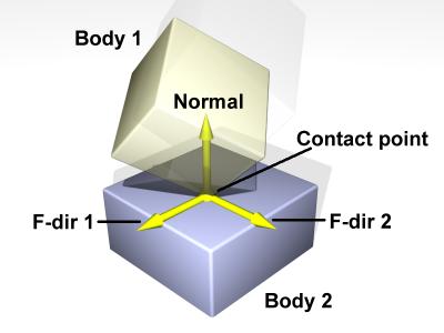
Figure 9: A contact joint.
The contact joint prevents body 1 and body 2 from inter-penetrating at the contact point. It does this by only allowing the bodies to have an ``outgoing'' velocity in the direction of the contact normal. Contact joints typically have a lifetime of one time step. They are created and deleted in response to collision detection.
接触ジョイントは、接触点で剛体1および剛体2が相互浸透するのを防 ぐ。それは単に、剛体がcontact normalの方向に初速度を持つことを可能にすることにより行う。接触ジョイントは、基本的に1回ステップする時間がかかる。それらは衝突検出に応じて 作成 され削除される。
接触ジョイントは、接触点で剛体1および剛体2が相互浸透するのを防 ぐ。それは単に、剛体がcontact normalの方向に初速度を持つことを可能にすることにより行う。接触ジョイントは、基本的に1回ステップする時間がかかる。それらは衝突検出に応じて 作成 され削除される。
Contact joints can simulate friction at the contact by applying special forces in the two friction directions that are perpendicular to the normal.
接触ジョイントはnormalに垂直な2つの摩擦の方向の特殊な力を用 いる ことよって、接触における摩擦をシミュレートすることができる。
接触ジョイントはnormalに垂直な2つの摩擦の方向の特殊な力を用 いる ことよって、接触における摩擦をシミュレートすることができる。
When a contact joint is created, a dContact structure must be supplied. This has the following definition:
接触ジョイントが生成される場合、dcontact構造体は定義されな けれ ばならない。これは次のように定義される:
接触ジョイントが生成される場合、dcontact構造体は定義されな けれ ばならない。これは次のように定義される:
struct dContact {
  dSurfaceParameters surface;
  dContactGeom geom;
  dVector3 fdir1;
};
geom is a substructure that is set by the collision functions. It is described in the collision section.
geomは衝突関数によってセットされる下部の構造体である。それは衝 突セクションに記述される。
geomは衝突関数によってセットされる下部の構造体である。それは衝 突セクションに記述される。
fdir1 is a "first friction direction" vector that defines a direction along which frictional force is applied. It must be of unit length and perpendicular to the contact normal (so it is typically tangential to the contact surface). It should only be defined if the dContactFDir1 flag is set in surface.mode. The "second friction direction" is a vector computed to be perpendicular to both the contact normal and fdir1.
fdir1は摩擦の力が適用される方向を定義する「第1の摩擦方向」ベ クトルである。それはユニット長さで、contact normalに垂直である(したがって、それは一般的には接触表面へ接線)。dContactFDir1フラグがsurface.modeの中でセットさ れる場合、それは単に定義される。「第2の摩擦方向」はcontact normalおよびfdir1の両方に垂直な方向で、計算されたベクトルである。
fdir1は摩擦の力が適用される方向を定義する「第1の摩擦方向」ベ クトルである。それはユニット長さで、contact normalに垂直である(したがって、それは一般的には接触表面へ接線)。dContactFDir1フラグがsurface.modeの中でセットさ れる場合、それは単に定義される。「第2の摩擦方向」はcontact normalおよびfdir1の両方に垂直な方向で、計算されたベクトルである。
surface is a substructure that is set by the user. Its members define the properties of the colliding surfaces. It has the following members:
surfaceはユーザによって設定される基本構造体である。そのメン バーは、衝突する表面の特性を定義する。次のメンバーを持っている:
int mode - Contact flags. This must always be set. This is a combination of one or more of the following flags:
surfaceはユーザによって設定される基本構造体である。そのメン バーは、衝突する表面の特性を定義する。次のメンバーを持っている:
int mode - Contact flags. This must always be set. This is a combination of one or more of the following flags:
- int mode - 接触用のフラグ。これは必ず設定する。これは以下のフラグの1つ以上の組み合わせである:
| dContactMu2 | If not set, use mu for both friction directions. If set, use mu for friction direction 1, use mu2 for friction direction 2.設定されない場合、両方の摩擦方向のためにmuを 用いる。設定すると、摩擦方向1はmu、摩擦方向2はmu2の設定が使用される。 |
| dContactFDir1 | If set, take fdir1 as friction direction 1, otherwise automatically compute friction direction 1 to be perpendicular to the contact normal (in which case its resulting orientation is unpredictable).設定すると、摩擦方向1としてfdir1が用いら れ、そうでなけ れば、contact normalに垂直な摩擦方向1を自動的に計算する(その場合、その際に生じる方位は予測不能である)。 |
| dContactBounce | If set, the contact surface is bouncy, in other words the bodies will bounce off each other. The exact amount of bouncyness is controlled by the bounce parameter.設定すると、接触表面は弾性になる。言い換えれ ば、剛体がお互いに反発するようになる。弾力性質の正確な量は、反発係数によって制御される。 |
| dContactSoftERP | If set, the error reduction parameter of the contact normal can be set with the soft_erp parameter. This is useful to make surfaces soft.設定するとき、contact normalのエラー縮小パラメータ(ERP)はsoft_erp変数と一緒に設定できる。これはやわらかい表面を表現するの役立つ。 |
| dContactSoftCFM | If set, the constraint force mixing parameter of the contact normal can be set with the soft_cfm parameter. This is useful to make surfaces soft.設定するとき、contact normalの強制力混合パラメータ(CFM)はsoft_cfm変数と一緒に設定できる。これはやわらかい表面を表現するの役立つ。 |
| dContactMotion1 | If set, the contact surface is assumed to be moving independently of the motion of the bodies. This is kind of like a conveyor belt running over the surface. When this flag is set, motion1 defines the surface velocity in friction direction 1.設定すると、接触表面が剛体の運動の独立した動き として仮定される。これは、表面上にベルトコンベヤが走ることに、何となく似ている。 |
| dContactMotion2 | The same thing as above, but for friction direction 2.上記と同じであるが、摩擦方向2のための設定とな る。 |
| dContactSlip1 | Force-dependent-slip (FDS) in friction direction 1.摩擦方向1の力依存スリップ(FDS) |
| dContactSlip2 | Force-dependent-slip (FDS) in friction direction 2.摩擦方向2の力依存スリップ(FDS) |
| dContactApprox1_1 | Use the friction pyramid approximation for friction direction 1. If this is not specified then the constant-force-limit approximation is used (and mu is a force limit).摩擦方向1のために摩擦ピラミッド近似値を使用す る。これがそのとき指定されない場合、一定の力限界近似が使用される(muは力の限界)。 |
| dContactApprox1_2 | Use the friction pyramid approximation for friction direction 2. If this is not specified then the constant-force-limit approximation is used (and mu is a force limit).摩擦方向2のために摩擦ピラミッド近似値を使用す る。これがそのとき指定されない場合、一定の力限界近似が使用される(muは力の限界)。 |
| dContactApprox1 | Equivalent to both dContactApprox1_1 and dContactApprox1_2. dContactApprox1_1と dContactApprox1_2の両方について同じにする。 |
- dReal mu : Coulomb friction coefficient. This must be in the range 0 to dInfinity. 0 results in a frictionless contact, and dInfinity results in a contact that never slips. Note that frictionless contacts are less time consuming to compute than ones with friction, and infinite friction contacts can be cheaper than contacts with finite friction. This must always be set.:クーロン摩擦係数。これは0からdInfinity[無限 大]の範囲である。0は摩擦がない接触の結果で、そしてdInfinityはスリップしない接触の結果となる。摩擦がない接触は摩擦がある時の計算より、 少ない時間であることに注意する。そして、無限の摩擦接触は、有限の摩擦との接触よりも早くなりうる。これは常にセットであることによる。
- dReal mu2 : Optional Coulomb friction coefficient for friction direction 2 (0..dInfinity). This is only set if the corresponding flag is set in mode.:摩擦方向2用のオプションのクーロン摩擦係数(0.. dInfinity)。対応するフラグがmodeでセットされる場合、これは単にセットされる。
- dReal bounce : Restitution parameter (0..1). 0 means the surfaces are not bouncy at all, 1 is maximum bouncyness. This is only set if the corresponding flag is set in mode.:反発係数(0..1)。0は、表面が全く弾力性のないことを 意味し、1は最大の弾力性のある性質である。対応するフラグがmodeでセットされる場合、これは単にセットされる。
- dReal bounce_vel : The minimum incoming velocity necessary for bounce (in m/s). Incoming velocities below this will effectively have a bounce parameter of 0. This is only set if the corresponding flag is set in mode.:反発(in m/s)に必要な最小の衝突する速度。真下に衝突する速度は、有効な0の反発係数を持つだろう。対応するフラグがmodeでセットされる場合、これは単に セットされる。
- dReal soft_erp : Contact normal ``softness'' parameter. This is only set if the corresponding flag is set in mode.:通常接触の"柔軟性"パラメータ。対応するフラグがmode でセットされる場合、これは単にセットされる。
dReal soft_cfm : Contact normal ``softness'' parameter. This is only set if the corresponding flag is set in mode.:通常接触の"柔軟性"パラメータ。対応するフラグがmode でセットされる場合、これは単にセットされる。
- dReal motion1,motion2 : Surface velocity in friction directions 1 and 2 (in m/s). These are only set if the corresponding flags are set in mode.:摩擦方向1および2(in m/s)の面速度。対応するフラグがmodeでセットされる場合、これらは単にセットされる。
- dReal slip1,slip2 : The coefficients of force-dependent-slip (FDS) for friction directions 1 and 2. These are only set if the corresponding flags are set in mode.:摩擦方向1および2のための力依存のスリップ係数 (FDS)。対応するフラグがmodeでセットされる場合、これらは単にセットされる。
FDS is an effect that causes the contacting surfaces to side past each other with a velocity that is proportional to the force that is being applied tangentially to that surface.
FDSは表面の接線方向に働く力に比例する速度と、お互いにサ イドを越えて表面に接触を起こす効力である。
FDSは表面の接線方向に働く力に比例する速度と、お互いにサ イドを越えて表面に接触を起こす効力である。
Consider a contact point where the coefficient of friction mu is infinite. Normally, if a force f is applied to the two contacting surfaces, to try and get them to slide past each other, they will not move. However, if the FDS coefficient is set to a positive value k then the surfaces will slide past each other, building up to a steady velocity of k*f relative to each other.
Note that this is quite different from normal frictional effects: the force does not cause a constant acceleration of the surfaces relative to each other - it causes a brief acceleration to achieve the steady velocity.
This is useful for modeling some situations, in particular tires. For example consider a car at rest on a road. Pushing the car in its direction of travel will cause it to start moving (i.e. the tires will start rolling). Pushing the car in the perpendicular direction will have no effect, as the tires do not roll in that direction. However - if the car is moving at a velocity v, applying a force f in the perpendicular direction will cause the tires to slip on the road with a velocity proportional to f*v (Yes, this really happens).
To model this in ODE set the tire-road contact parameters as follows: set friction direction 1 in the direction that the tire is rolling in, and set the FDS slip coefficient in friction direction 2 to k*v, where v is the tire rolling velocity and k is a tire parameter that you can chose based on experimentation.
Note that FDS is quite separate from the sticking/slipping effects of Coulomb friction - both modes can be used together at a single contact point.
7.3.8. Angular Motor 角度モータ
An angular motor (AMotor) allows the relative angular velocities of two bodies to be controlled. The angular velocity can be controlled on up to three axes, allowing torque motors and stops to be set for rotation about those axes (see the ``Stops and motor parameters'' section below). This is mainly useful in conjunction will ball joints (which do not constrain the angular degrees of freedom at all), but it can be used in any situation where angular control is needed. To use an AMotor with a ball joint, simply attach it to the same two bodies that the ball joint is attached to.
角度モータ(AMotor)は2つの剛体の相対角速度をコントロールす ることができる。角速度は3方向の軸上でコントロールすることができ、これらの軸についての回転を設定することでトルクモータと停止が可能となる(下記の "停止およびモータ・パラメータ"のセクションを参照してください)。これはボールジョイントの接続において主に有効である(角度の自由度をまったく拘束 してないとき)。しかし、これは角度調整が必要とされるいくつかの場面では使われる。ボールジョイントを備えたAMotorを使用するためには、単に、 ボールジョイントが付けられた同じ2つの剛体にそれを付ける。
角度モータ(AMotor)は2つの剛体の相対角速度をコントロールす ることができる。角速度は3方向の軸上でコントロールすることができ、これらの軸についての回転を設定することでトルクモータと停止が可能となる(下記の "停止およびモータ・パラメータ"のセクションを参照してください)。これはボールジョイントの接続において主に有効である(角度の自由度をまったく拘束 してないとき)。しかし、これは角度調整が必要とされるいくつかの場面では使われる。ボールジョイントを備えたAMotorを使用するためには、単に、 ボールジョイントが付けられた同じ2つの剛体にそれを付ける。
The AMotor can be used in different modes. In dAMotorUser mode, the user directly sets the axes that the AMotor controls. In dAMotorEuler mode, AMotor computes the euler angles corresponding to the relative rotation, allowing euler angle torque motors and stops to be set. An AMotor joint with euler angles is shown in figure 10.
AMotorは異なるモードで使用することができる。 dAMotorUserモードにおいて、ユーザはAMotorが制御する軸を直接設定する。dAMotorEulerモードにおいて、AMotorは相対 的な回転に対応するeuler角度を計算し、euler角度のトルクモータおよびストップが設定可能である。euler角度を備えたAMotorジョイン トは図10に示す。
AMotorは異なるモードで使用することができる。 dAMotorUserモードにおいて、ユーザはAMotorが制御する軸を直接設定する。dAMotorEulerモードにおいて、AMotorは相対 的な回転に対応するeuler角度を計算し、euler角度のトルクモータおよびストップが設定可能である。euler角度を備えたAMotorジョイン トは図10に示す。
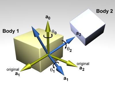
Figure 10: An AMotor joint with euler angles.
In this diagram, a0, a1 and a2 are the three axes along which angular motion is controlled. The green axes (including a0) are anchored to body 1. The blue axes (including a2) are anchored to body 2. To get the body 2 axes from the body 1 axes the following sequence of rotations is performed:
- Rotate by theta 0 about a0.
- Rotate by theta 1 about a1 (a1 has been rotated from its original position).
- Rotate by theta 2 about a2 (a2 has been rotated twice from its original position).
There is an important restriction when using euler angles: the theta 1 angle must not be allowed to get outside the range - pi /2 ... pi /2. If this happens then the AMotor joint will become unstable (there is a singularity at +/- pi /2). Thus you must set the appropriate stops on axis number 1.
void dJointSetAMotorMode (dJointID, int mode);
int dJointGetAMotorMode (dJointID);
Set (and get) the angular motor mode. The mode parameter must be one of the following constants:
角度モータ・モードを設定(取得)する。modeパラメータは次の定数 のうちの1つを設定する:
角度モータ・モードを設定(取得)する。modeパラメータは次の定数 のうちの1つを設定する:
| dAMotorUser | The AMotor axes and joint angle settings are entirely controlled by the user. This is the default mode.AMotor軸とジョイント角度の設定は、ユーザによって 完全に制御される。これはデフォルト・モードである。 |
| dAMotorEuler | Euler angles are automatically computed. The axis a1 is also automatically computed. The AMotor axes must be set correctly when in this mode, as described below. When this mode is initially set the current relative orientations of the bodies will correspond to all euler angles at zero.オイラー角は自動的に計算される。軸a1も自動的に計算さ れる。以下に記述において、このモード中にいる場合、AMotor軸は正確に設定される。このモードが最初にセットされる時、剛体の現在の相対的な方位は 0ですべてのオイラー角に相当する。 |
void dJointSetAMotorNumAxes (dJointID, int num);
int dJointGetAMotorNumAxes (dJointID);
Set (and get) the number of angular axes that will be controlled by the AMotor. The argument num can range from 0 (which effectively deactivates the joint) to 3. This is automatically set to 3 in dAMotorEuler mode.
void dJointSetAMotorAxis (dJointID, int anum, int rel,
		  dReal x, dReal y, dReal z);
void dJointGetAMotorAxis (dJointID, int anum, dVector3 result);
int dJointGetAMotorAxisRel (dJointID, int anum);
Set (and get) the AMotor axes. The anum argument selects the axis to change (0,1 or 2). Each axis can have one of three ``relative orientation'' modes, selected by rel:
- 0: The axis is anchored to the global frame.
- 1: The axis is anchored to the first body.
- 2: The axis is anchored to the second body.
The axis vector (x,y,z) is always specified in global coordinates regardless of the setting of rel. There are two GetAMotorAxis functions, one to return the axis and one to return the relative mode.
For dAMotorEuler mode:
- Only axes 0 and 2 need to be set. Axis 1 will be determined automatically at each time step.
- Axes 0 and 2 must be perpendicular to each other.
- Axis 0 must be anchored to the first body, axis 2 must be anchored to the second body.
void dJointSetAMotorAngle (dJointID, int anum, dReal angle);
Tell the AMotor what the current angle is along axis anum. This function should only be called in dAMotorUser mode, because in this mode the AMotor has no other way of knowing the joint angles. The angle information is needed if stops have been set along the axis, but it is not needed for axis motors.
AMotorにanum軸に沿った現在の角度の状態を伝える。このモー ドにおいて、AMotorがジョイント角度を知る他の方法を持たないので、この関数はdAMotorUserモードで単に呼ばれる。停止が軸に沿って設定 された場合、角度情報は必要であるが、モータ軸のには必要としない。
AMotorにanum軸に沿った現在の角度の状態を伝える。このモー ドにおいて、AMotorがジョイント角度を知る他の方法を持たないので、この関数はdAMotorUserモードで単に呼ばれる。停止が軸に沿って設定 された場合、角度情報は必要であるが、モータ軸のには必要としない。
dReal dJointGetAMotorAngle (dJointID, int anum);
Return the current angle for axis anum. In dAMotorUser mode this is simply the value that was set with dJointSetAMotorAngle. In dAMotorEuler mode this is the corresponding euler angle.
dReal dJointGetAMotorAngleRate (dJointID, int anum);
Return the current angle rate for axis anum. In dAMotorUser mode this is always zero, as not enough information is available. In dAMotorEuler mode this is the corresponding euler angle rate.
7.4. General
The joint geometry parameter setting functions should only be called after the joint has been attached to bodies, and those bodies have been correctly positioned, otherwise the joint may not be initialized correctly. If the joint is not already attached, these functions will do nothing.
ジョイントの幾何学パラメータの設定する関数はジョイントの剛体の接続 を行った後でなければならない。そして、それらの剛体は正確な位置を持っている。そうでなければ、ジョイントは正確に初期化されない可能性がある。もし、 ジョイントがまだ接続されてない場合、これらの関数は何もしない。
ジョイントの幾何学パラメータの設定する関数はジョイントの剛体の接続 を行った後でなければならない。そして、それらの剛体は正確な位置を持っている。そうでなければ、ジョイントは正確に初期化されない可能性がある。もし、 ジョイントがまだ接続されてない場合、これらの関数は何もしない。
For the parameter getting functions, if the system is out of alignment (i.e. there is some joint error) then the anchor/axis values will be correct with respect to body 1 only (or body 2 if you specified body 1 as zero in the dJointAttach function).
The default anchor for all joints is (0,0,0). The default axis for all joints is (1,0,0).
When an axis is set it will be normalized to unit length. The adjusted axis is what the axis getting functions will return.
When measuring a joint angle or position, a value of zero corresponds to the initial position of the bodies relative to each other.
Note that there are no functions to set joint angles or positions (or their rates) directly, instead you must set the corresponding body positions and velocities.
7.5. Stop and motor parameters ストップとモータパラメータ
When a joint is first created there is nothing to prevent it from moving through its entire range of motion. For example a hinge will be able to move through its entire angle, and a slider will slide to any length.
ジョイントが初めて生成されたときは、動きの全範囲において移動を防ぐ ものは何もない。例えば、ヒンジはその全角度を通って移動することができる。また、スライダーは任意の長さで動く。
ジョイントが初めて生成されたときは、動きの全範囲において移動を防ぐ ものは何もない。例えば、ヒンジはその全角度を通って移動することができる。また、スライダーは任意の長さで動く。
This range of motion can be limited by setting stops on the joint. The joint angle (or position) will be prevented from going below the low stop value, or from going above the high stop value. Note that a joint angle (or position) of zero corresponds to the initial body positions.
動きの範囲はジョイントのストップを設定することで拘束できる。ジョイ ント角度(位置)は下限ストップ値を下まわるか、上限ストップ値を上まわってから防がれる。注意することとして、ゼロのジョイント角度(位置)は初期の剛 体のポジションに相当する。
動きの範囲はジョイントのストップを設定することで拘束できる。ジョイ ント角度(位置)は下限ストップ値を下まわるか、上限ストップ値を上まわってから防がれる。注意することとして、ゼロのジョイント角度(位置)は初期の剛 体のポジションに相当する。
As well as stops, many joint types can have motors. A motor applies a torque (or force) to a joint's degree(s) of freedom to get it to pivot (or slide) at a desired speed. Motors have force limits, which means they can apply no more than a given maximum force/torque to the joint.
ストップと同様に、多くのジョイントの種類はモータを持つことができ る。モータは希望の速度で回転(スライド)させるために自由度のジョイント角度(s)にトルク(力)を与える。
ストップと同様に、多くのジョイントの種類はモータを持つことができ る。モータは希望の速度で回転(スライド)させるために自由度のジョイント角度(s)にトルク(力)を与える。
Motors have two parameters: a desired speed, and the maximum force that is available to reach that speed. This is a very simple model of real life motors, engines or servos. However, is it quite useful when modeling a motor (or engine or servo) that is geared down with a gearbox before being connected to the joint. Such devices are often controlled by setting a desired speed, and can only generate a maximum amount of power to achieve that speed (which corresponds to a certain amount of force available at the joint).
モータには2つのパラメータがある:希望の速度、そして指定速度範囲内 で利用可能な最大の力である。これは実際のエンジン・サーボモータのとても単純なモデルである。しかしながら、ジョイントに接続される前のギヤボックスで 減速させたモータ(エンジン・サーボ)の場合には、大いに有用である。そのような装置は、希望の速度設定で頻繁に制御され、その速度を達成する最大量の力 を単に生成することができる(ジョイントで利用可能なある量の力に相当するどれか)。
モータには2つのパラメータがある:希望の速度、そして指定速度範囲内 で利用可能な最大の力である。これは実際のエンジン・サーボモータのとても単純なモデルである。しかしながら、ジョイントに接続される前のギヤボックスで 減速させたモータ(エンジン・サーボ)の場合には、大いに有用である。そのような装置は、希望の速度設定で頻繁に制御され、その速度を達成する最大量の力 を単に生成することができる(ジョイントで利用可能なある量の力に相当するどれか)。
Motors can also be used to accurately model dry (or Coulomb) friction in joints. Simply set the desired velocity to zero and set the maximum force to some constant value - then all joint motion will be impeded by that force.
The alternative to using joint stops and motors is to simply apply forces to the affected bodies yourself. Applying motor forces is easy, and joint stops can be emulated with restraining spring forces. However applying forces directly is often not a good approach and can lead to severe stability problems if it is not done carefully.
Consider the case of applying a force to a body to achieve a desired velocity. To calculate this force you use information about the current velocity, something like this:
force = k * (desired speed - current speed)
force = k * (desired speed - current speed)
This has several problems. First, the parameter k must be tuned by hand. If it is too low the body will take a long time to come up to speed. If it is too high the simulation will become unstable. Second, even if k is chosen well the body will still take a few time steps to come up to speed. Third, if any other ``external'' forces are being applied to the body, the desired velocity may never even be reached (a more complicated force equation would be needed, which would have extra parameters and its own problems).
Joint motors solve all these problems: they bring the body up to speed in one time step, provided that does not take more force than is allowed. Joint motors need no extra parameters because they are actually implemented as constraints. They can effectively see one time step into the future to work out the correct force. This makes joint motors more computationally expensive than computing the forces yourself, but they are much more robust and stable, and far less time consuming to design with. This is especially true with larger rigid body systems.
Similar arguments apply to joint stops.
7.5.1. Parameter Functions
Here are the functions that set stop and motor parameters (as well as other kinds of parameters) on a joint:
ジョイントにおいての停止とモータのパラメータ(他の種類のパラメータ と同様)を設定する関数:
ジョイントにおいての停止とモータのパラメータ(他の種類のパラメータ と同様)を設定する関数:
void dJointSetHingeParam (dJointID, int parameter, dReal value);
void dJointSetSliderParam (dJointID, int parameter, dReal value);
void dJointSetHinge2Param (dJointID, int parameter, dReal value);
void dJointSetUniversalParam (dJointID, int parameter, dReal value);
void dJointSetAMotorParam (dJointID, int parameter, dReal value);
dReal dJointGetHingeParam (dJointID, int parameter);
dReal dJointGetSliderParam (dJointID, int parameter);
dReal dJointGetHinge2Param (dJointID, int parameter);
dReal dJointGetUniversalParam (dJointID, int parameter);
dReal dJointGetAMotorParam (dJointID, int parameter);
Set/get limit/motor parameters for each joint type. The parameter numbers are:
書くジョイントの種類に対して限界/モータ パラメータの設定/取得する。パラメータ番号は次のとおり:
書くジョイントの種類に対して限界/モータ パラメータの設定/取得する。パラメータ番号は次のとおり:
| dParamLoStop | Low stop angle or position. Setting this to -dInfinity (the default value) turns off the low stop. For rotational joints, this stop must be greater than - pi to be effective.角度か位置の下限。-dInfinity(デフォルト値) を設定すると下限をなくす。回転するジョイントについては、この限度は有効にするには-piより大きくなければはならない。 |
| dParamHiStop | High stop angle or position. Setting this to dInfinity (the default value) turns off the high stop. For rotational joints, this stop must be less than pi to be effective. If the high stop is less than the low stop then both stops will be ineffective. 角度か位置の上限。dInfinity(デフォルト値)を 設定すると上限をなくす。回転するジョイントについては、この限度が有効にするにはpi未満でなければならない。下限より大きく、上限より小さい場合、両 方の拘束は効果を持たない。 |
| dParamVel | Desired motor velocity (this will be an angular or linear velocity). 希望のモータ速度(これは角速度か線形速度になる)。 |
| dParamFMax | The maximum force or torque that the motor will use to achieve the desired velocity. This must always be greater than or equal to zero. Setting this to zero (the default value) turns off the motor. 希望速度に達するためにモータが使用する最大の力またはトルク。これはいつもに0以上である。0(デフォルト値)に設定するとモータは動かない。 |
| dParamFudgeFactor | The current joint stop/motor implementation has a small problem: when the joint is at one stop and the motor is set to move it away from the stop, too much force may be applied for one time step, causing a ``jumping'' motion. This fudge factor is used to scale this excess force. It should have a value between zero and one (the default value). If the jumping motion is too visible in a joint, the value can be reduced. Making this value too small can prevent the motor from being able to move the joint away from a stop.現在のジョイントの停止/モータの技術は少し問題がある: ジョイントが1つの停止にあり、モータは、停止から動くように設定した場合、あまりに力が必要となり、1ステップで適用され、その結果"飛ぶ"動作を引き 起こす。このあいまいな要因はこの過剰な力を計るために使用される。それは、0と1(デフォルト値)の間の値で設定する。飛ぶ動作がジョイントにおいて目 障りな場合、値は縮小することができる。この値を小さくしすぎると、モータが停止からジョイントを動かすことできなくなるかもしれない。 |
| dParamBounce | The bouncyness of the stops. This is a restitution parameter in the range 0..1. 0 means the stops are not bouncy at all, 1 means maximum bouncyness. 停止の弾力性。これは範囲0..1の範囲の反発係数であ る。0はすべてで弾力がなくなり、1は弾力性が最大であることを意味する。 |
| dParamCFM | The constraint force mixing (CFM) value used when not at a stop. 停止でない場合に使用される拘束力混合(CFM)値。 |
| dParamStopERP | The error reduction parameter (ERP) used by the stops. 停止で使用されるエラー縮小パラメータ(ERP)。 |
| dParamStopCFM | The constraint force mixing (CFM) value used by the stops. Together with the ERP value this can be used to get spongy or soft stops. Note that this is intended for unpowered joints, it does not really work as expected when a powered joint reaches its limit. 停止で使用される拘束力混合(CFM)値。ERP値と一緒 に、これは吸収性・柔軟性をもった停止を得るために使用できる。ここで注意することは、これは動力を持たないジョイントのために提供される。動力が供給さ れたジョイントがその限界に到着する場合、実際に予定通りに作動しない。 |
| dParamSuspensionERP | Suspension error reduction parameter (ERP). Currently this is only implemented on the hinge-2 joint.サスペンションのエラー縮小パラメーター(ERP)。現 在、これはhinge-2だけに使用される。 |
| dParamSuspensionCFM | Suspension constraint force mixing (CFM) value. Currently this is only implemented on the hinge-2 joint.サスペンションの拘束力混合(CFM)。現在、これは hinge-2だけに使用される。 |
If a particular parameter is not implemented by a given joint, setting it will have no effect.
特別なパラメータが、与えられたジョイントによって実行されない場合、 それの設定は効果がない。
特別なパラメータが、与えられたジョイントによって実行されない場合、 それの設定は効果がない。
These parameter names can be optionally followed by a digit (2 or 3) to indicate the second or third set of parameters, e.g. for the second axis in a hinge-2 joint, or the third axis in an AMotor joint. A constant dParamGroup is also defined such that: dParamXi = dParamX + dParamGroup * (i-1)
7.6. Setting Joint Torques/Forces Directly
Motors (see above) allow you to set joint velocities directly. However, you may instead wish to set the torque or force at a joint instead. These functions do just that. Note that they don't affect the motor, but simply call dBodyAddForce/dBodyAddTorque on the bodies attached to it.
モータ(上記参照)は、ジョイントの速度を直接設定することができる。 しかしながら、ジョイントでトルクか力を代わりに設定したいと思うかもしれない。これらの関数は単にそれをする。それらはモータに影響しないが、それに付 けられた剛体上のdBodyAddForce /dBodyAddTorqueを単に呼ぶことに注意する。
モータ(上記参照)は、ジョイントの速度を直接設定することができる。 しかしながら、ジョイントでトルクか力を代わりに設定したいと思うかもしれない。これらの関数は単にそれをする。それらはモータに影響しないが、それに付 けられた剛体上のdBodyAddForce /dBodyAddTorqueを単に呼ぶことに注意する。
dJointAddHingeTorque(dJointID joint, dReal torque)
Applies the torque about the hinge axis. That is, it applies a torque with magnitude torque, in the direction of the hinge axis, to body 1, and with the same magnitude but in opposite direction to body 2. This function is just a wrapper for dBodyAddTorque
dJointAddUniversalTorques(dJointID joint, dReal torque1, dReal torque2)
Applies torque1 about the universal's axis 1, and torque2 about the universal's axis 2. This function is just a wrapper for dBodyAddTorque.
dJointAddSliderForce(dJointID joint, dReal force)
Applies the given force in the slider's direction. That is, it applies a force with magnitude force, in the direction slider's axis, to body1, and with the same magnitude but opposite direction to body2. This function is just a wrapper for dBodyAddForce.
dJointAddHinge2Torques(dJointID joint, dReal torque1, dReal torque2)
Applies torque1 about the hinge2's axis 1, and torque2 about the hinge2's axis 2. This function is just a wrapper for dBodyAddTorque.
dJointAddAMotorTorques(dJointID joint, dReal torque0, dReal torque1,
                      dReal torque2)
Applies torque0 about the AMotor's axis 0, torque1 about the AMotor's axis 1, and torque2 about the AMotor's axis 2. If the motor has fewer than three axes, the higher torques are ignored. This function is just a wrapper for dBodyAddTorque.